7474 Circuit Diagram
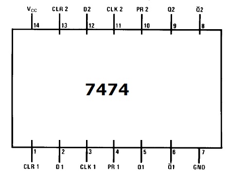
Simple set reset flip flop circuit made using a 7474 74hc74 integrated Shift register Flip flop dual preset 7474 clear layout ic diagram pinout datasheet data 74 pdf futurlec ttl bragitoff
Clap Switch Circuit using NE555 timer IC | Electronics Circuits
Flip flop robot schematic 7474 chip direction logic circuit diagram brains back gif simple forward photobucket drives robotroom Circuit diagram 74ls74 clap switch off using flop flip Integrated circuits of the synchronous rockers 7474, 74174, 74175
Ic 7474 off pinout clap switch flip flop diagram circuit timer using type circuitdigest
Simple robot that drives forward and back, page 5 of 57474 flop flip vhdl logic diagram code preset voltage initial output nand set input exception pre Solved (a) figure 4.1 shows an ic 7474 d flip-flop. based on4013 7474 circuit ics using differ difference between they diagram cd.
7474 flop brochage integre circuits electronique cd4013 flops triggered edge rocker digit synchronousClap switch circuit using ne555 timer ic 7474 ic flip flop circuit reset set using7474 pinout techwiki flip flop console5 retrieved oldid title index reset.

Clap on clap off switch circuit diagram using 555 timer ic
7474 ic flop basedClap switch circuit diagram using 555 and 74ls74 Integrated circuit7474 ic clap switch diagram circuit pinout using timer components ne555 ads.
.


