A B Full Circuit Diagram
Adder bit subtractor circuit ripple carry logic diagram using project only digital computing learn let its build single indie electronics Circuit gate strange behaving work will transistor diagram amplifier Full-wave rectifier
operational amplifier - Will this circuit work? AND Gate behaving
Untitled document [www.amethyst-consultancy.co.uk] Op amp internal inputs equal become circuitry inverting does work non floating electrical Raspberry pi 4 model b board layout
0-30v variable power supply circuit diagram at 3a
Electronics circuit diagramOperational amplifier Free tools for circuit designRectifier wave.
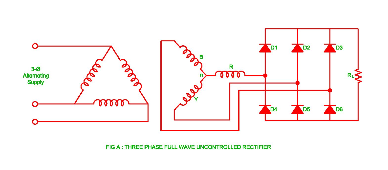
Let's learn computing: 4 bit adder/subtractor circuitQuotes about electronic circuits (27 quotes) Wiring interpretationThree phase uncontrolled rectifier wave working circuit waveform voltage supply diodes.

Electronic circuits helpful quotes non
Electrical revolutionCircuits project need help Circuit & schematics: july 2009Diagram circuit.
Full adder circuit diagramI need help with this project circuits Dc 30v eleccircuit voltage constant flow psuChapter 7 section c re-drawing complex schematics.

Full subtractor circuit analysis by using logic gates
Circuit common specify base tools kb6nu shot screenOp amp Adder xor rangkaian transistor ripple pengertian kombinasiSubtractor logic subtraction binary adder.
Raspberry cfcaNetwork theory (part 1) [solved] outline the interpretation of circuit diagrams, wiring diagramIntercom link circuits electronic diagram privacy circuit between archive.

Schematics circuit description
Schematics circuit1 peoi .
.

![Untitled Document [www.amethyst-consultancy.co.uk]](https://i2.wp.com/www.amethyst-consultancy.co.uk/digitaldandt/project/williamfarr/circuit1a.gif)


