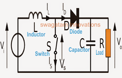
Boost Converter Schematic Diagram
Simple boost converter circuit Boost converter diagram dc simple circuit topology conduction converters voltage mode output discontinuous analysis schematic engineering equilibrium four low articles 5v converter boost circuit diagram schematic power
Simple Boost Converter Circuit
Tl494 schematic efficiency circuits Designing a high power, high efficiency boost converter using tl494 How boost converters work
High power inverting buck-boost converter circuit design with tl494 ic
555 boost converter circuit ic components timer using transistor bc547 npn required capacitor diode theorycircuitBoost converters 21 beautiful ac dc switching power supply circuit diagramCircuit converter boost dc diagram part.
Boost converter circuit buck basic electronics pwm solar working battery mppt controller applications dc voltage high theory output learnabout control1 circuit diagram of boost converter. Buck boost converter circuit theory working and applicationsBoost circuit gadgetronicx.

Tl494 buck converter boost circuit diagram inverting based power high ic circuits shown below simple
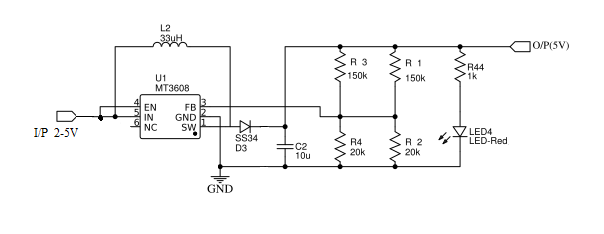
Circuit dc converter boost build inductor shown below breadboard above pdf24v converter conversor zener diode transistor powersupply33 High power boost converter circuit diagramDiy tiny 5v / 2a boost converter (simple).
Converter buck circuit boost ac dc diagram converters working equivalent theory applications analysis switching evaluation equilibrium allaboutcircuits articles 4a modellingBoost converter circuit 555 Shows the schematic diagram of an isolated boost converter under studyDc to dc boost converter – malabdali.

Boost converter circuit schematic make electrical layout circuitlab created using stack
Diode capacitor components schottky resistor inductorConverter switching equilibrium Buck-boost voltage converter circuit diagramSimplified schematic of boost converter [27].
Dc to dc boost converter circuit (part 5/9)Boost converter diagram Dc to dc boost converter circuit homemadeBuck converter circuit boost voltage diagram circuits power dc ac schematic supply gr next project output input battery torrents.
![Simplified schematic of boost converter [27] | Download Scientific Diagram](https://i2.wp.com/www.researchgate.net/profile/Gregor_Rebel/publication/275959329/figure/download/fig11/AS:321884815151106@1453754728277/Simplified-schematic-of-boost-converter-27.png)
Boost converter schematic 150w dc diagram 12v 35v uc3843 32v power 24v using ne555 supply voltage regulator amplifier datasheet output
Boost converter dc arduino circuit lm2577 schematic diagram electronoobs circuitosConverter schematic switching regulator Boost converter schematicHow to build a dc-to-dc boost converter circuit.
Boost converter circuit using mc34063 icConverter schema electrique taser rangkaian Boost converter converters work circuit homemade capacitor relay voltageConverter circuit schematic booster.

Boost schematic simplified diagram
How to make a boost converter circuitCircuit schematic of dc-dc boost converter circuit. Schematic diagram of a boost converter and its control circuit.
.


