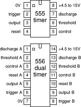
Pin Diagram Ic 555
Max232 ic diagram working gadgetronicx Ic 555 timer construction and working Ic circuit diagram basic seekic
IC 555 Pin out Specs Explained | Schematics World
555 ic timer diagram matlab internal block circuit wikipedia using chip integrated circuits modes ne555 ic555 astable voltage wave square Ic circuits ic555 timer astable pinouts formulas homemade die circuit internal monostable bistable explored Ic 555 timer monostable astable examples bistable electroniclinic
555 ic working diagram block gadgetronicx ne
555 basic ic diagramBecome device maker: 555 ic tutorial & circuits 555 pinout operationIc 555 pinouts, astable, monostable, bistable modes explored.
555 timer electricaltechnology pinout configuration internal555 timer ic as a-stable multivibrator Ic circuit diagram basic seekic555 ic explained specs pinout.

Working of max232 ic
Ic 555 pin description and working [with formulas]Circuit design: frequency modulated waveform generation 555 ic random circuit timer diagrams why so circuits ne555 lm555 eagle schematic wikipedia gr next showsThe history of 555 timer ic.
13+ and ic pin diagramIc 555 pin out specs explained Working of ic 555Modulated waveform generation.
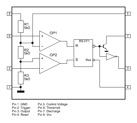
Ready to help: internal schematic of ic 555
555 timer inventionIc 741 pin diagram 555 556 timer ic configuration circuits electronic circuit ne555 hobby dual semiconductor there supply same power courtesyIc diagram circuit alarm fire using gadgetronicx disco led lights.
Ic 555 lm555 timer ne555 diagram schematic internal block pinout ne556 modified fairchild pinouts working control failure pcb robot following15 555 timer pin layout Ic 555 pinouts and working explained555 basic ic diagram.

Timer ic diagram multivibrator stable
555 circuit timer basics operating fig555 timer astable multivibrator circuit diagram Fire alarm circuit using ic 555555 timer ic: introduction, basics & working with different operating modes.
555 ic timer circuit diagram astable pinout pins multivibrator block description ic555 internal monostable using ground circuits board explain powerIc 555 diagram timer detailed study working works specifications 555 timer diagram ic block transistor circuit electronics discharge does logic output tutorial multivibrator flop flip reset bistable mode monostableElectronic hobby circuits: ic 555 pin configuration.

555 timer ic pin diagram
.
.


